
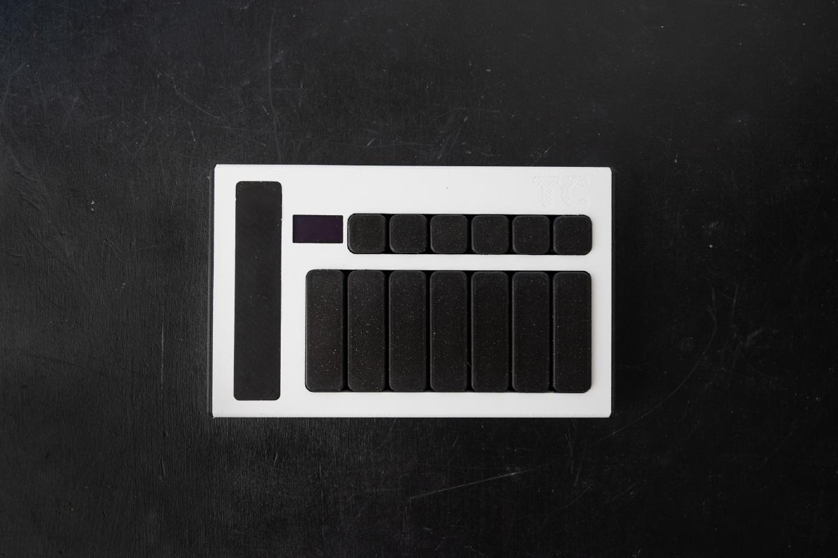
Introduction
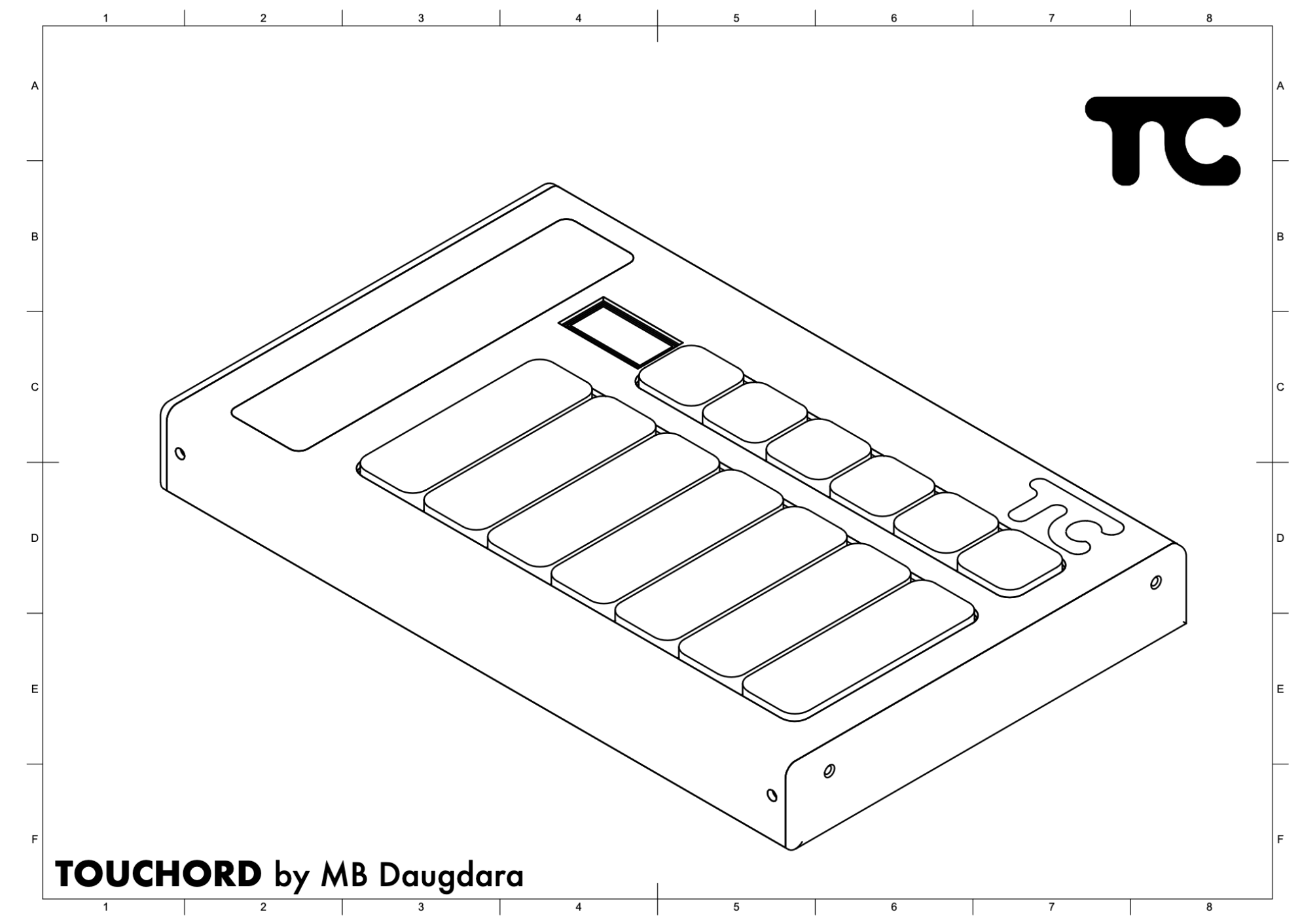
If you’ve already purchased a DIY Kit, continue, otherwise, Pre-order Touchord DIY Kit.
Assembly time
Prints usually take around 6-8h to complete, depending on the printer, materials and print quality. There may be some re-prints due to tolerances not being perfect. Assembly itself is 1-2h, depending on experience.
Parts needed
- Touchord PCB
- Bela Trill Bar
- SSD1306 display
- 13x Cherry MX-style Switches
- 7x 3U stabilizers
- 8x M2.5 8mm screws
- 4x M2.5 3mm screws
- 8x M2.5x8mm Brass inserts (Optional)
Tools needed
- 3D Printer with Filament (PETG recommended)
- Soldering Iron + Solder + Flux
- Screwdriver
- Epoxy Glue and Double-Sided tape
- M2.5 Drill Tap (Optional)
Disclaimer
This is an DIY hobbyist kit - not a finished product. Buyer assumes full responsibility for FCC/CE/EMC compliance in the final assembled device. Not for commercial resale without testing.
5V USB powered only. No warranty/liability for damage. Partial refunds only if unassembled.
Part 1: 3D Printing
All 3D printing parts are available: Parametric On MakerWorld (adjustable tolerances), On GitHub.
Parametric models are most useful for Keycaps, since their tolerances can be wonky due to small parts. Other parts’ tolerances could be adjusted depending if you want the screw-holes to fit Brass inserts, need extra tolerance for Trill Bar fitting, Key space, Display space.
Step 1: Printing Enclosure
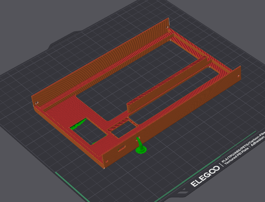
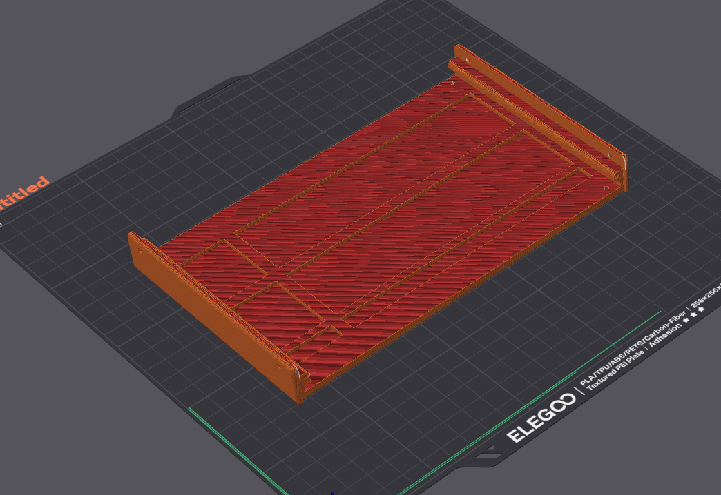
Enclosure needs to be printed With a flat plane on the print bed. I recommend using Tree supports for the Trill Bar space and connector.
Step 2: Printing Keys
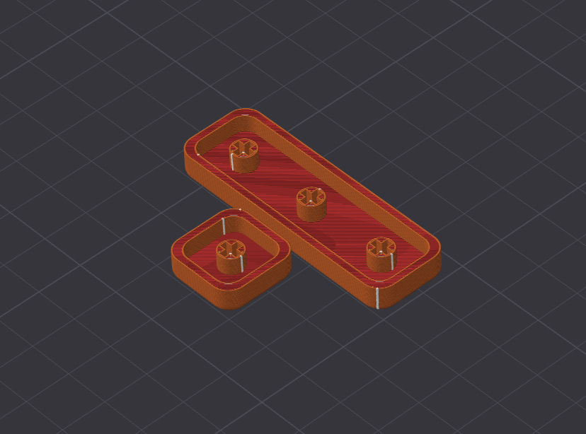
Keys are a tough print, since mounting holes are very sensitive to tolerances. I recommend doing test prints with different tolerances. They should be printed with the flat side on the print bed.
Step 3: Printing Key braces
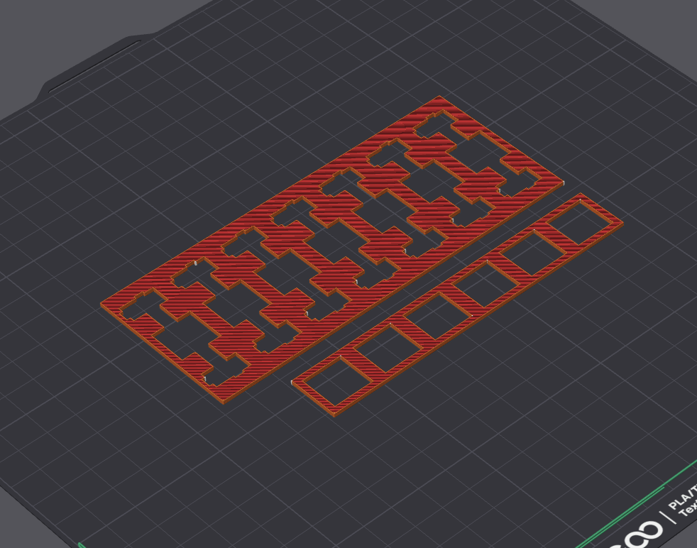
They’re straight-forward to print, as they are just flat.
Step 3.5: Clean-up your prints
Remove the supports, sand jagged edges, make your prints cleaner. They will be most of what you use and touch after all!
Part 2: Soldering
Step 4: Insert Switches and Stabilizers into the brace
First, assemble the 7 Stabilizers. I suggest following this video:
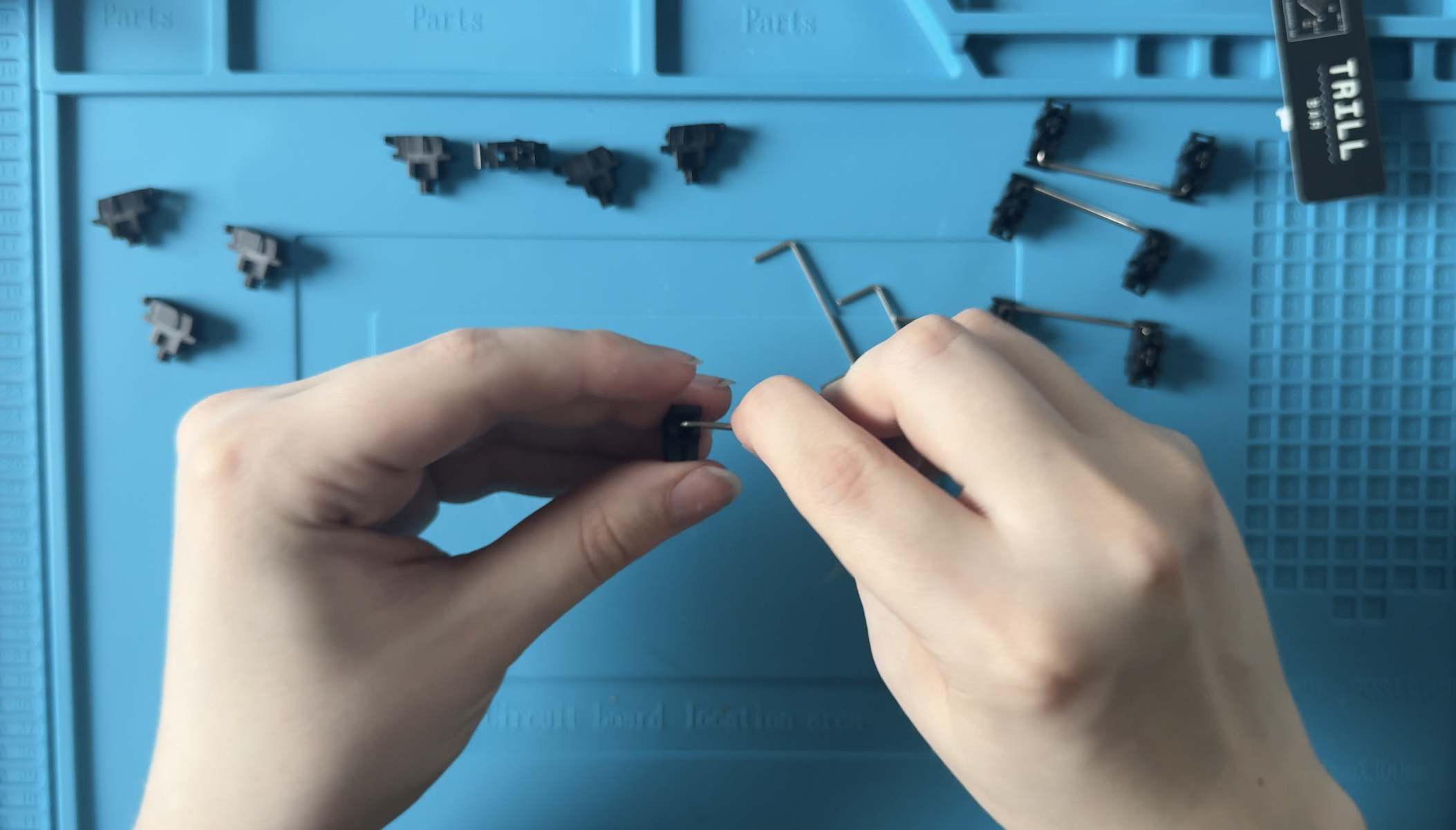
Insert the assembled stabilizers into the braces.
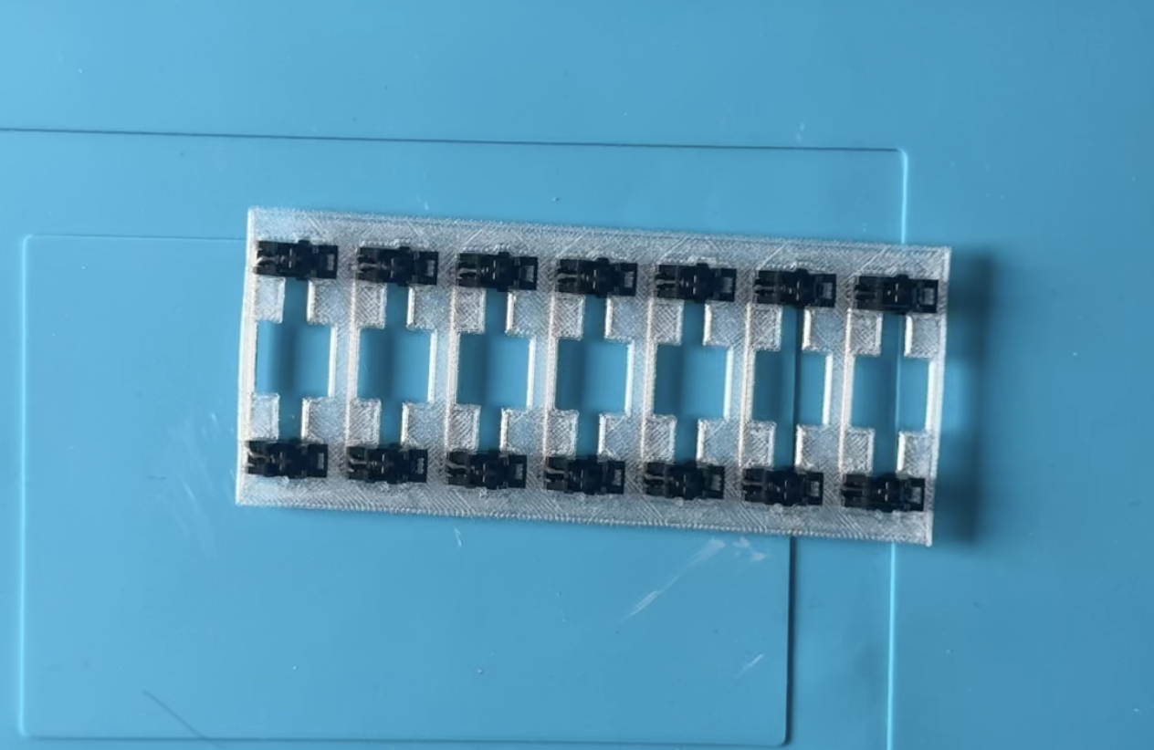
Then, insert the 7 switches themselves into the brace with 7 holes and stabilizers.
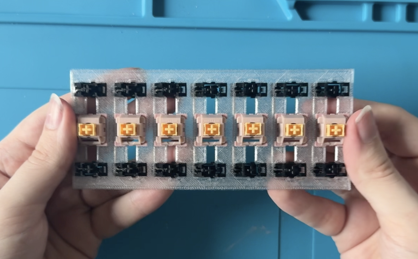
And last, insert the 6 switches into the brace with six holes.
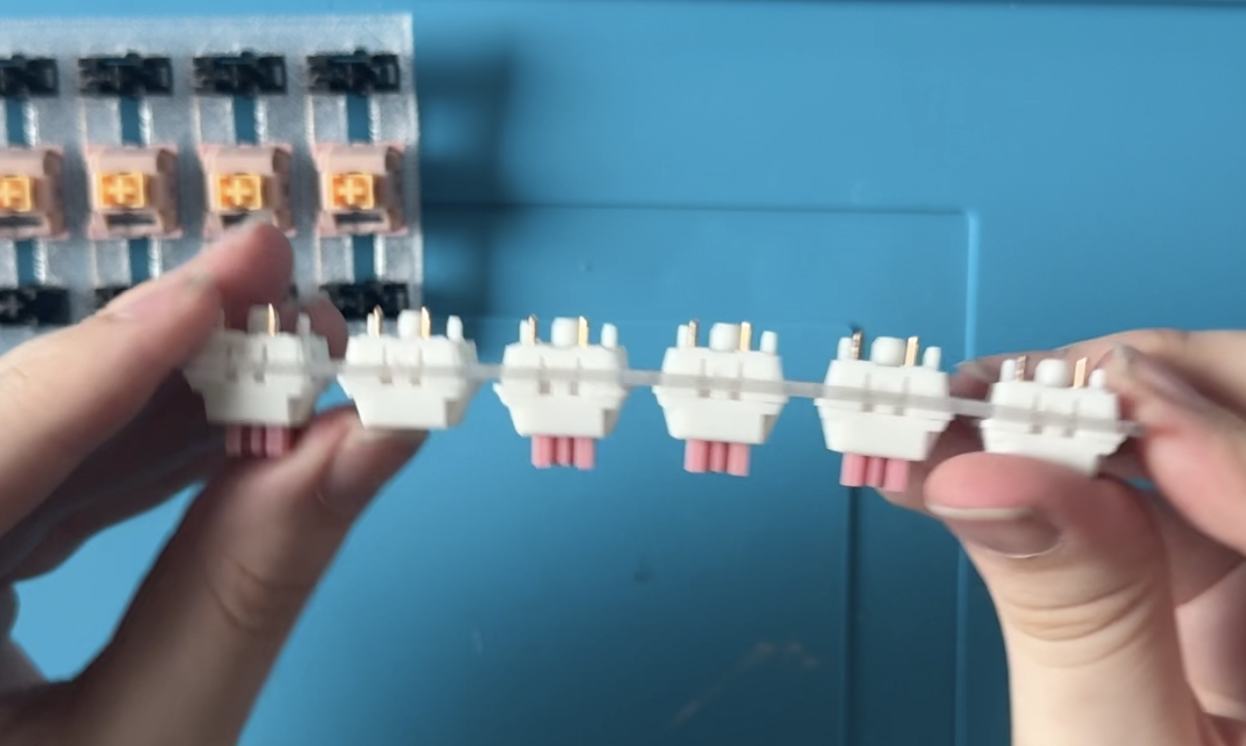
Step 5: Solder the Switches
In this step, I recommend you first align the switches on the PCB, so they are poking out evenly.
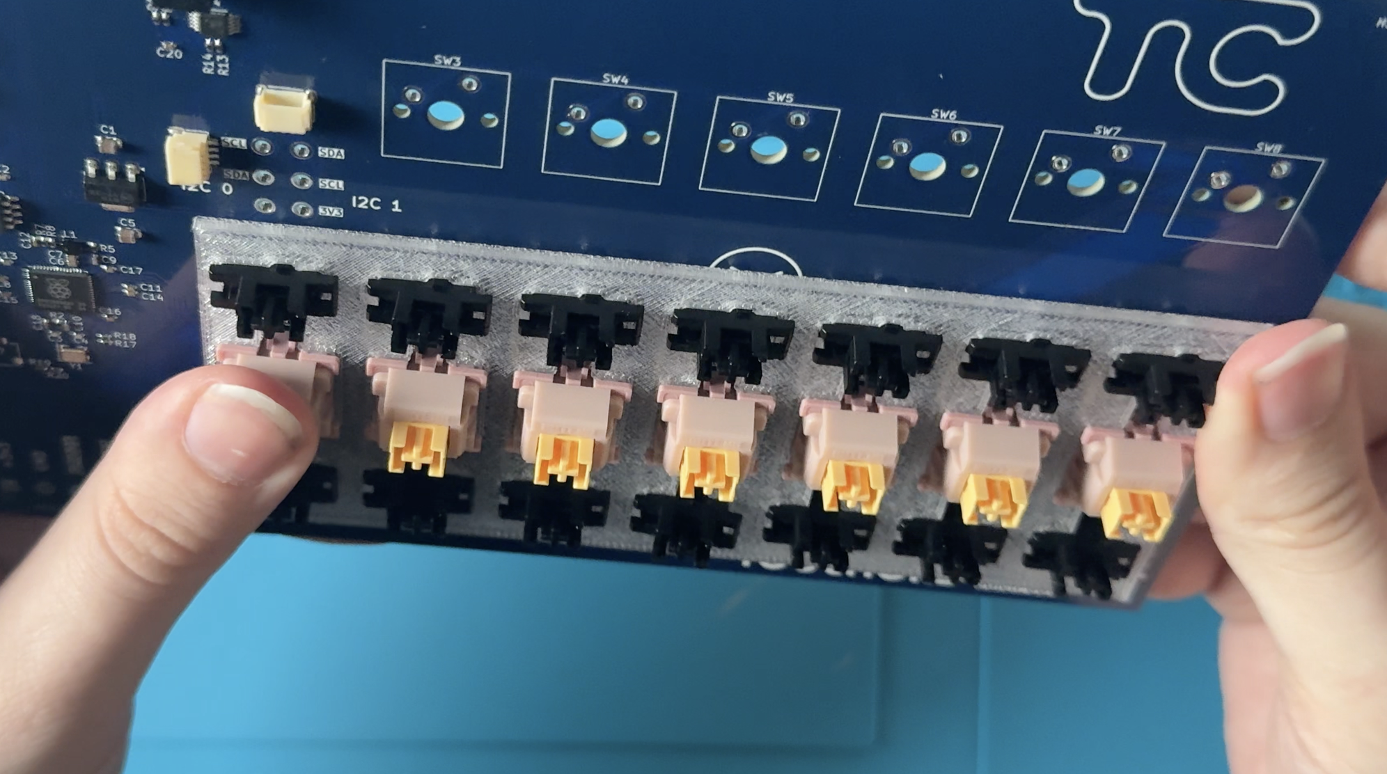
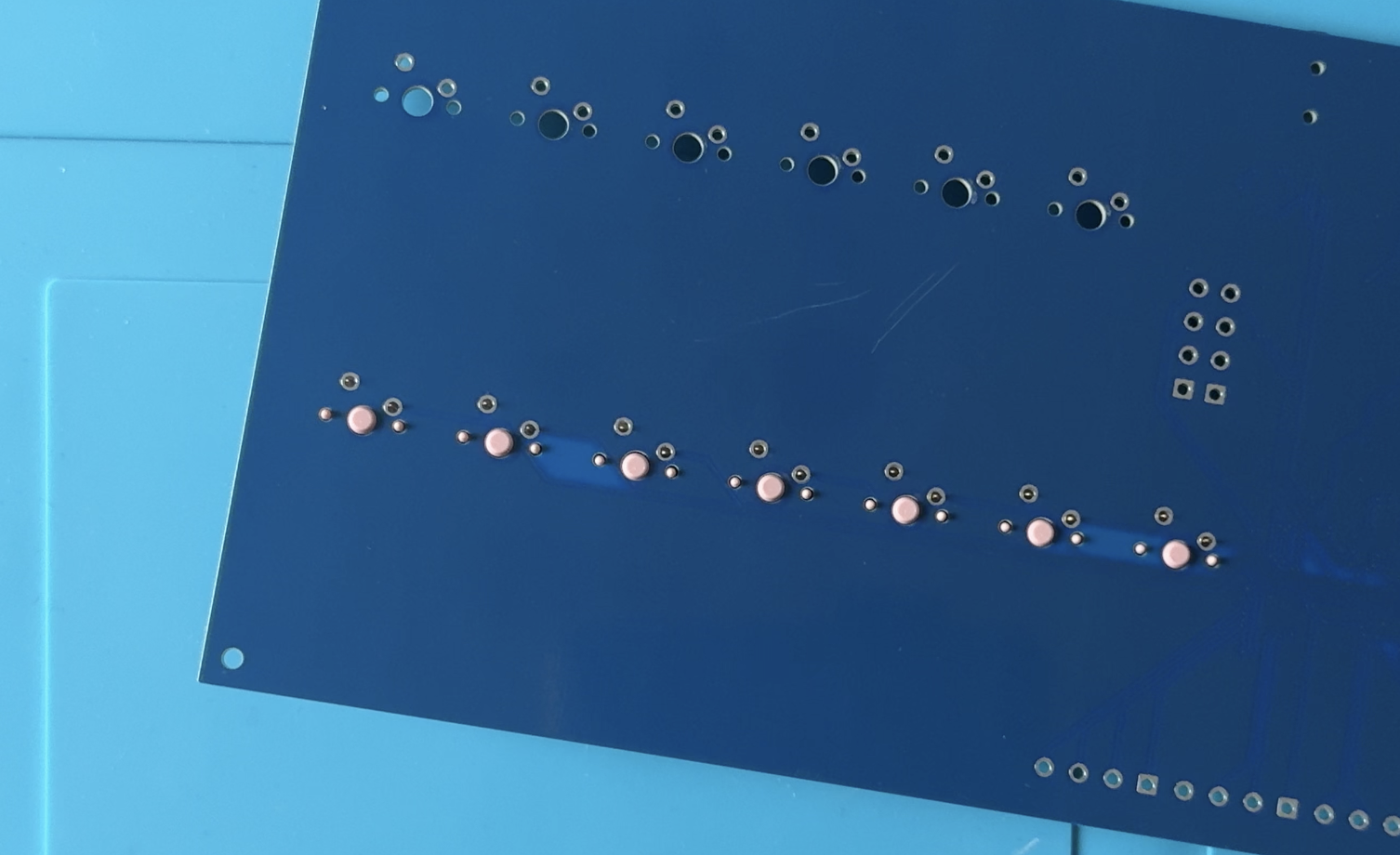
When soldering, add some flux and hold your soldering iron in one spot, feeding the solder into the hole, until you’ve got a nice solder joint. Make sure it isn’t loose, you cannot see any holes at the joint.
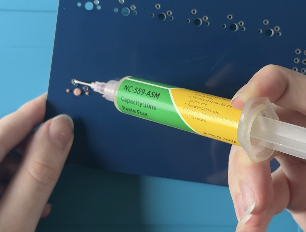
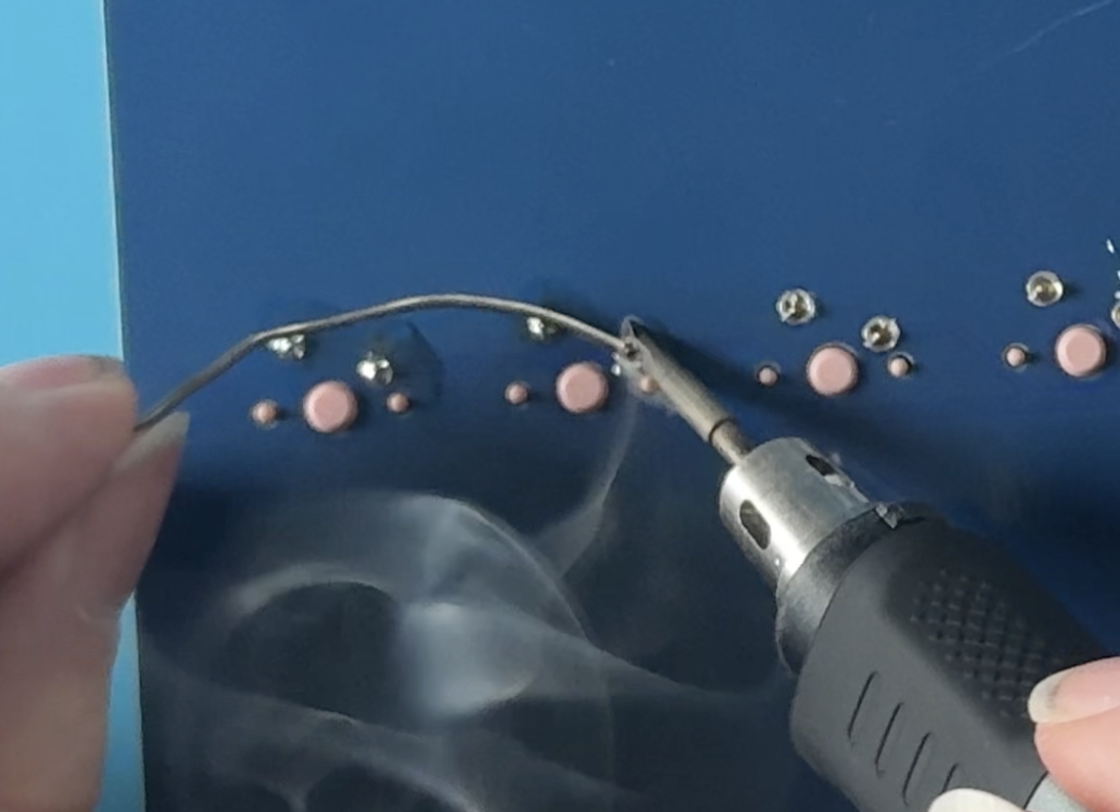
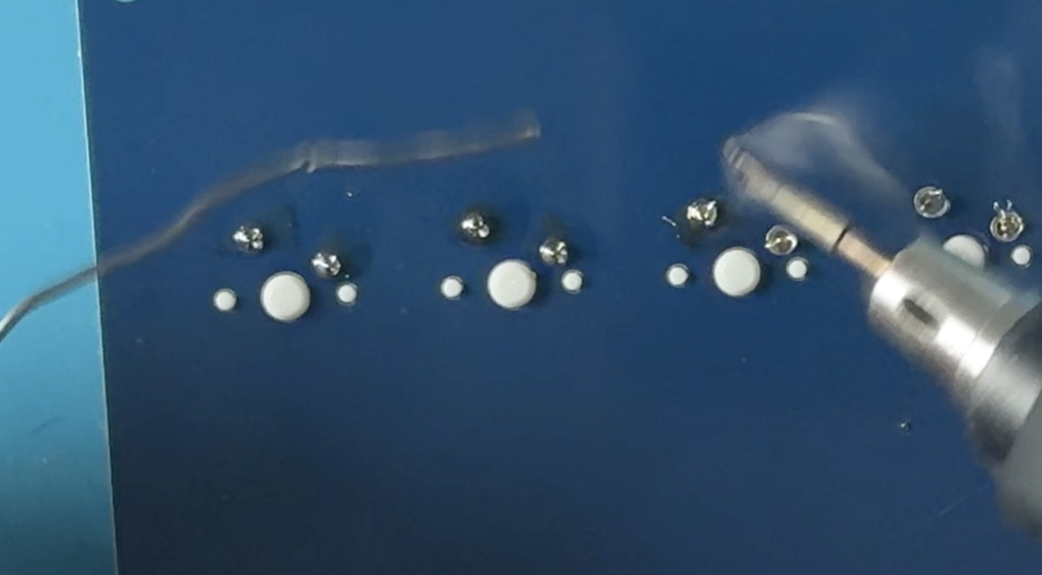
Step 6: Solder the Display connector
Display needs two things done: Header pins de-soldered and JST connector soldered.
To desolder the header pins, with a soldering iron Carefully Push out the pins, and with a pair of pliers, take the Header pins away. This is the end result:
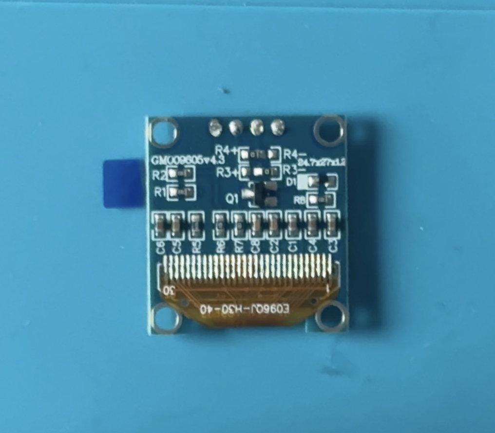
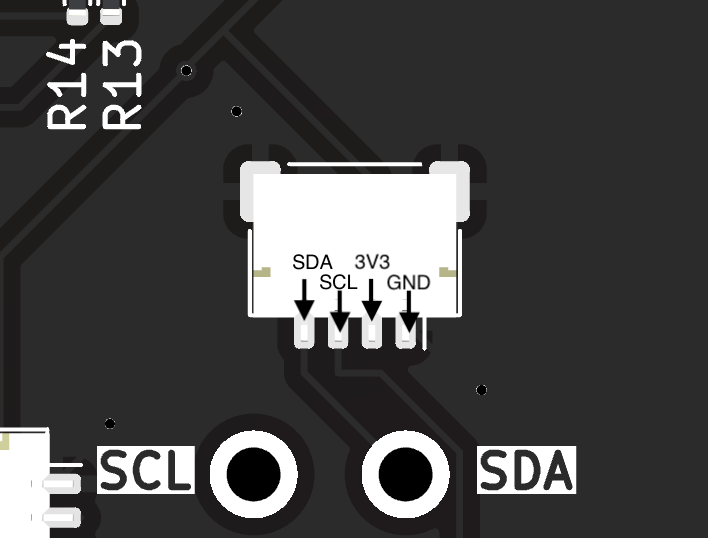
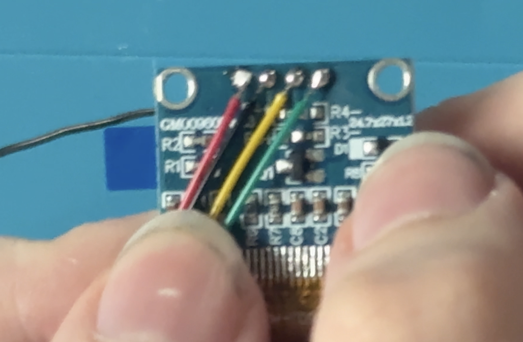
Soldering the connector is straight-forward. Take the JST connector and solder it’s wires to the pins of the Display, so that all connections match the PCB.
Mine ended up being with this color order:
Step 7: Test the board
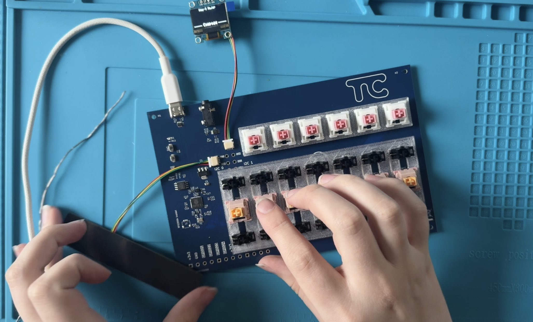
Plug in the Trill Bar (with the included double-sided JST/QWIIC Connector), the display, and plug the Touchord PCB into a computer with a DAW or a MIDI compatible program. Press the switches, to make sure connections are soldered correctly. Touch the Trill bar to see if it responds, and observe the display. If everything works, proceed.
Part 3: Assembly
Before assebly, unplug the display and Trill Bar from the PCB. You can test the Keycap fit at this stage, and re-print them with different tolerances if that is unsuccessful. They should move like keys on a keyboard. If the keys get stuck, the tolerances are off and the keycaps either have not fit correctly or there’s too much friction with the stabilizers.
If you plan on using Brass Inserts in this assembly, now is the time to insert them. Same with tapping the screw holes, now is the time.
Step 8: Mount the PCB to the Bottom Shell
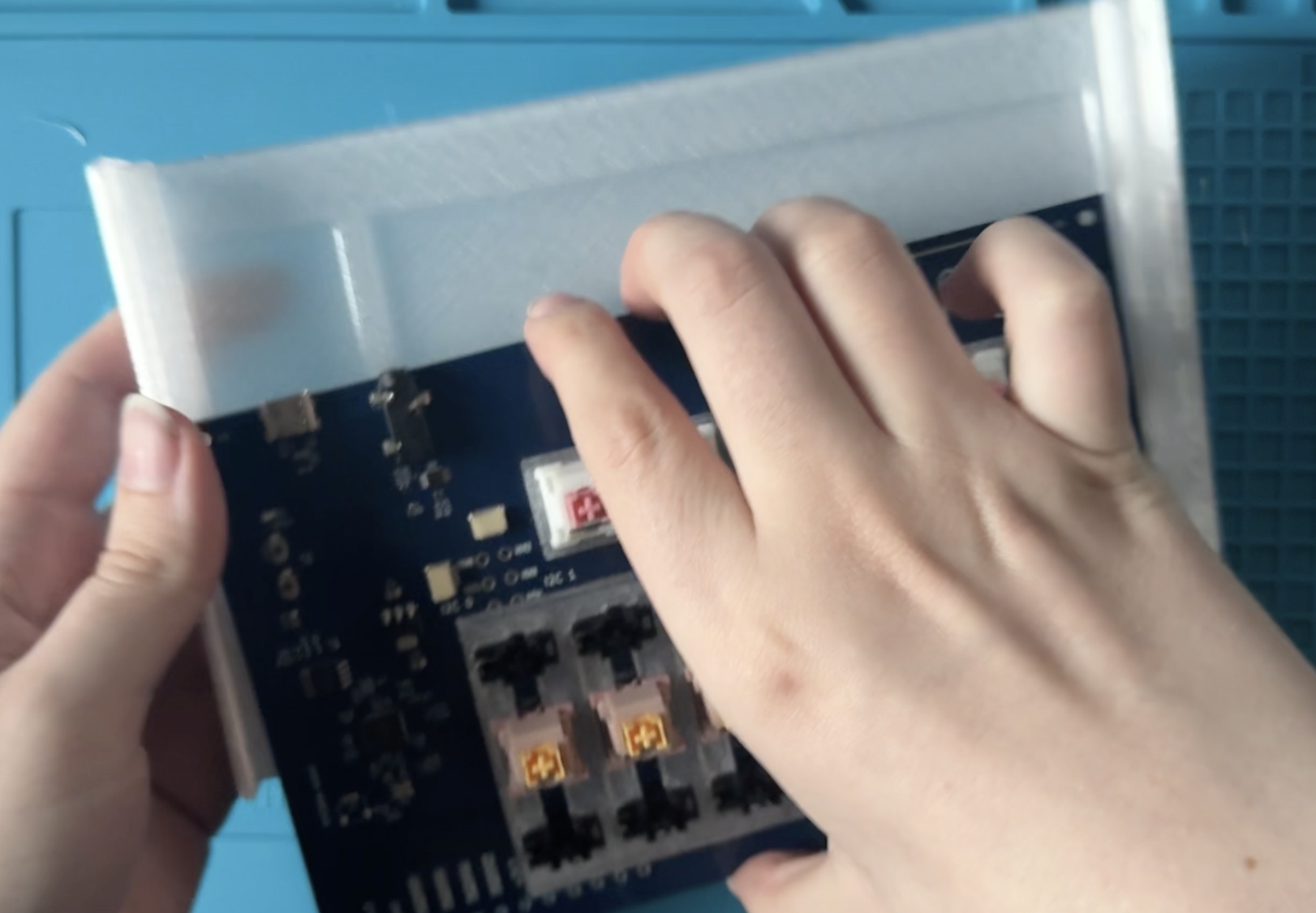
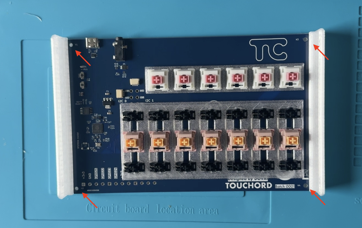
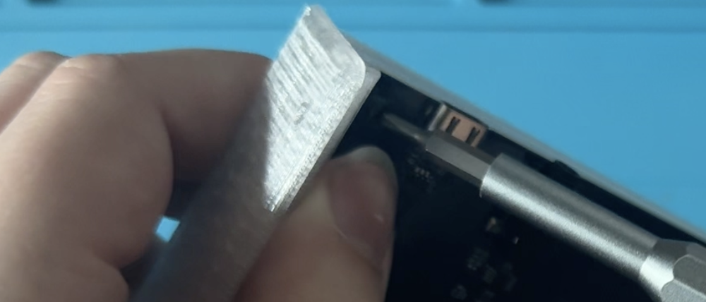
For this, take 4x M2.5 3mm screws (shortest). Place your PCB on the shell in this orientation and Secure the PCB with the screws:
Step 9: Glue the display to the Top Shell
Take your Display, align it in a way that makes the display centered on the Top Shell.
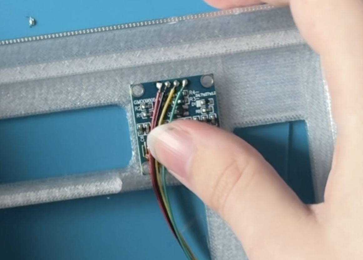
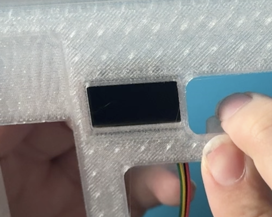
Then, use Epoxy Glue on the corners, to secure the display to the board. Note, this is Permanent, so do this step carefully, do not rush and let the Glue dry well.
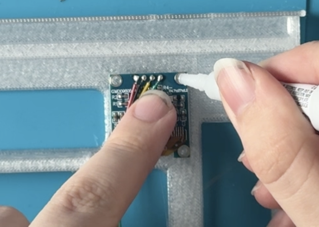
Step 10: Attach the Trill Bar to the Top Shell
Attatching the Trill Bar either goes two-ways, depending on your printer’s tolerances. If you place the bar in the designated space and it snaps in place, Perfect, you’re finished!
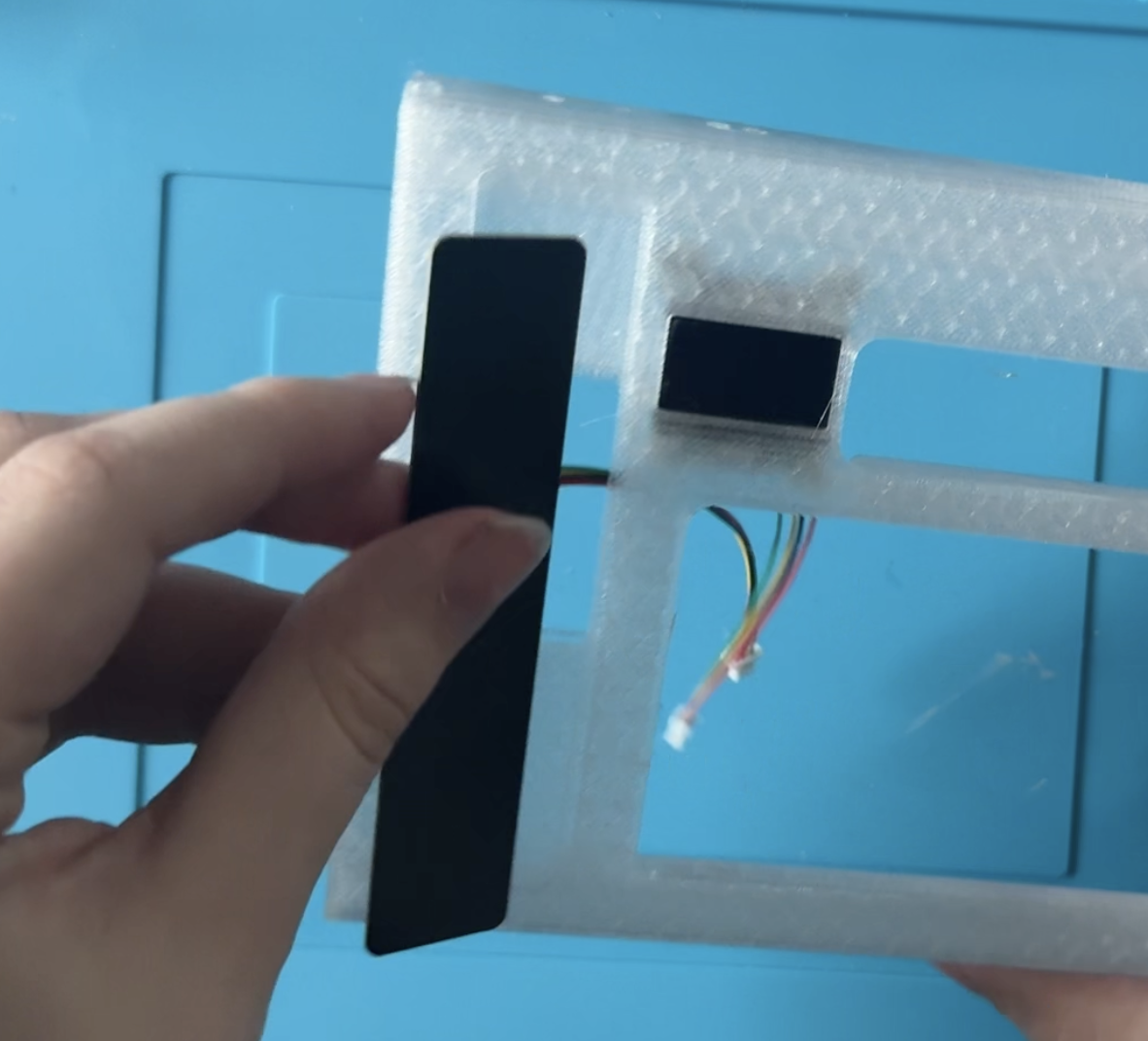
If you place the bar in the designated space and it’s loose, glue it on with double-sided tape, that way it’s secure and doesn’t move.
If you place the bar in the designated space and it doesn’t fit, your tolerance is off. Since this is a big print, and if you don’t want to print it again, you can either sand the edges of the Print, until it fits, or sanding the edges of the Trill Bar.
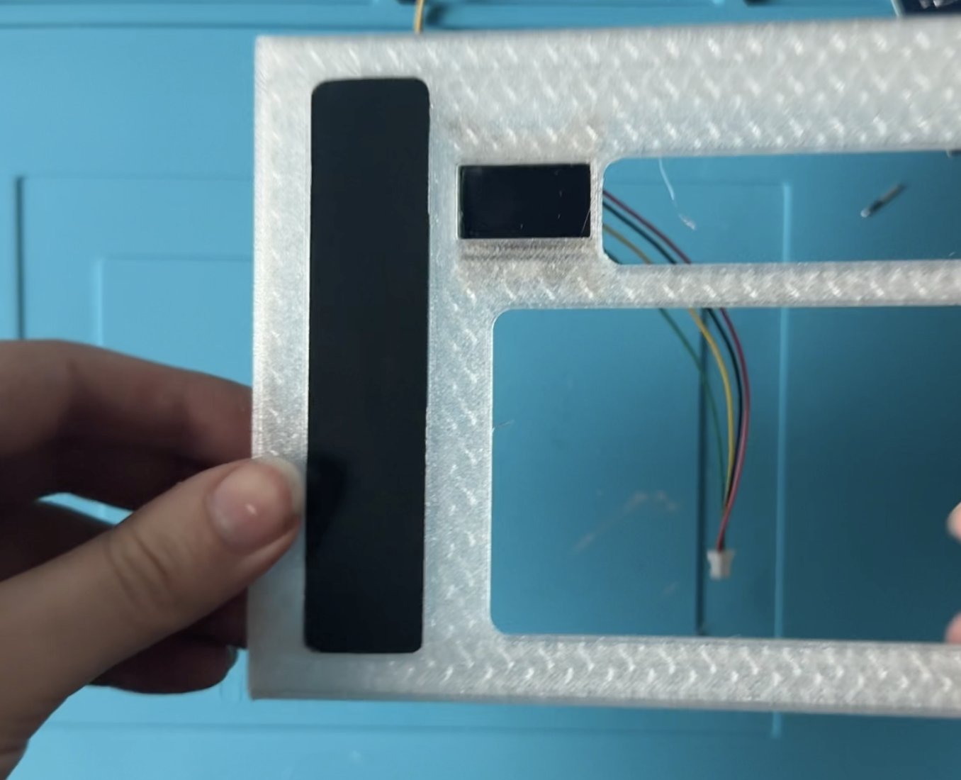
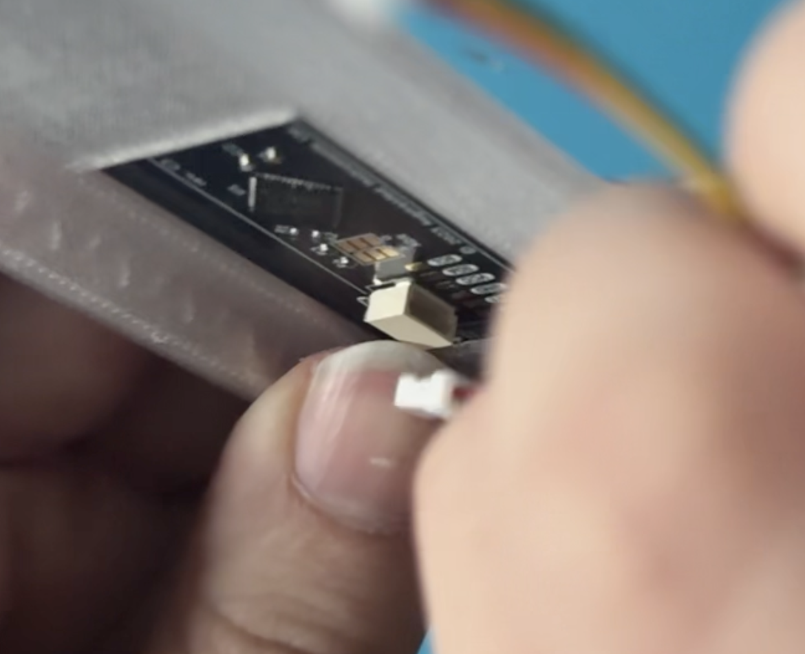
Step 11: Connect the Display and Trill Bar Connectors to PCB
Do it in the same way you did when testing the PCB.
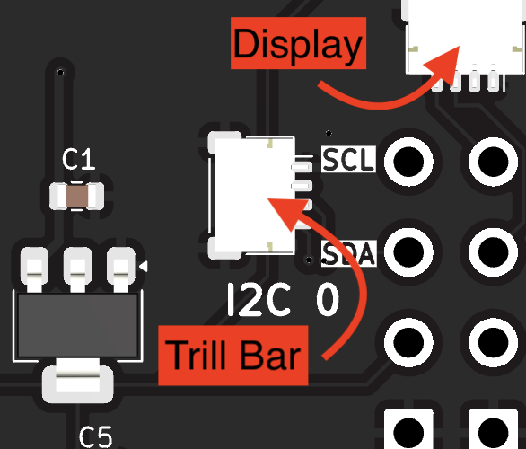
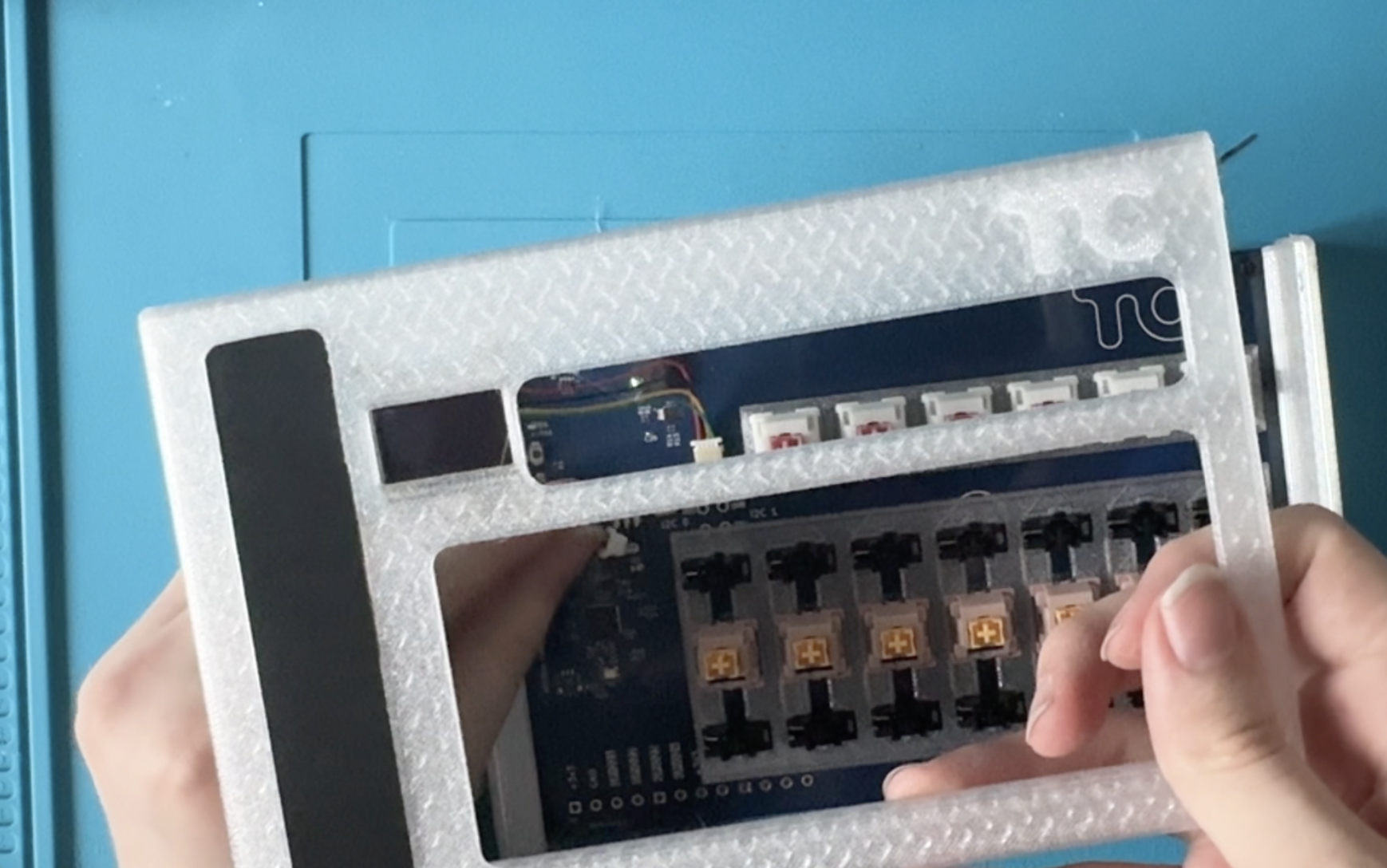
Step 12: Put the Top Shell on the Bottom Shell
Align everything so it is snug, all the connectors are accessible. You can test the Touchord again at this point.
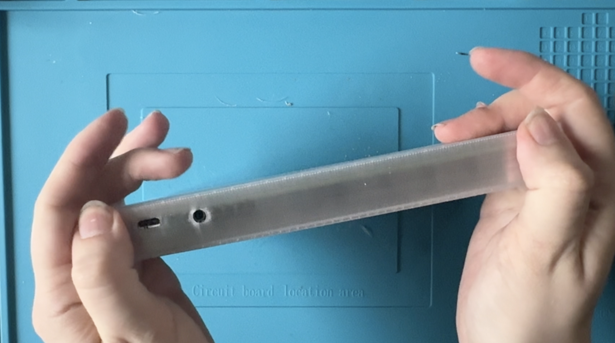
Step 13: Screw everything together
There are 8 remaining holes to screw. In the kits, these are the longer ones. I added Silver self-tapping screws, if you don’t tap the holes or don’t add the Brass Inserts. Take the screws and screw them into the 8 exposed screw-holes.
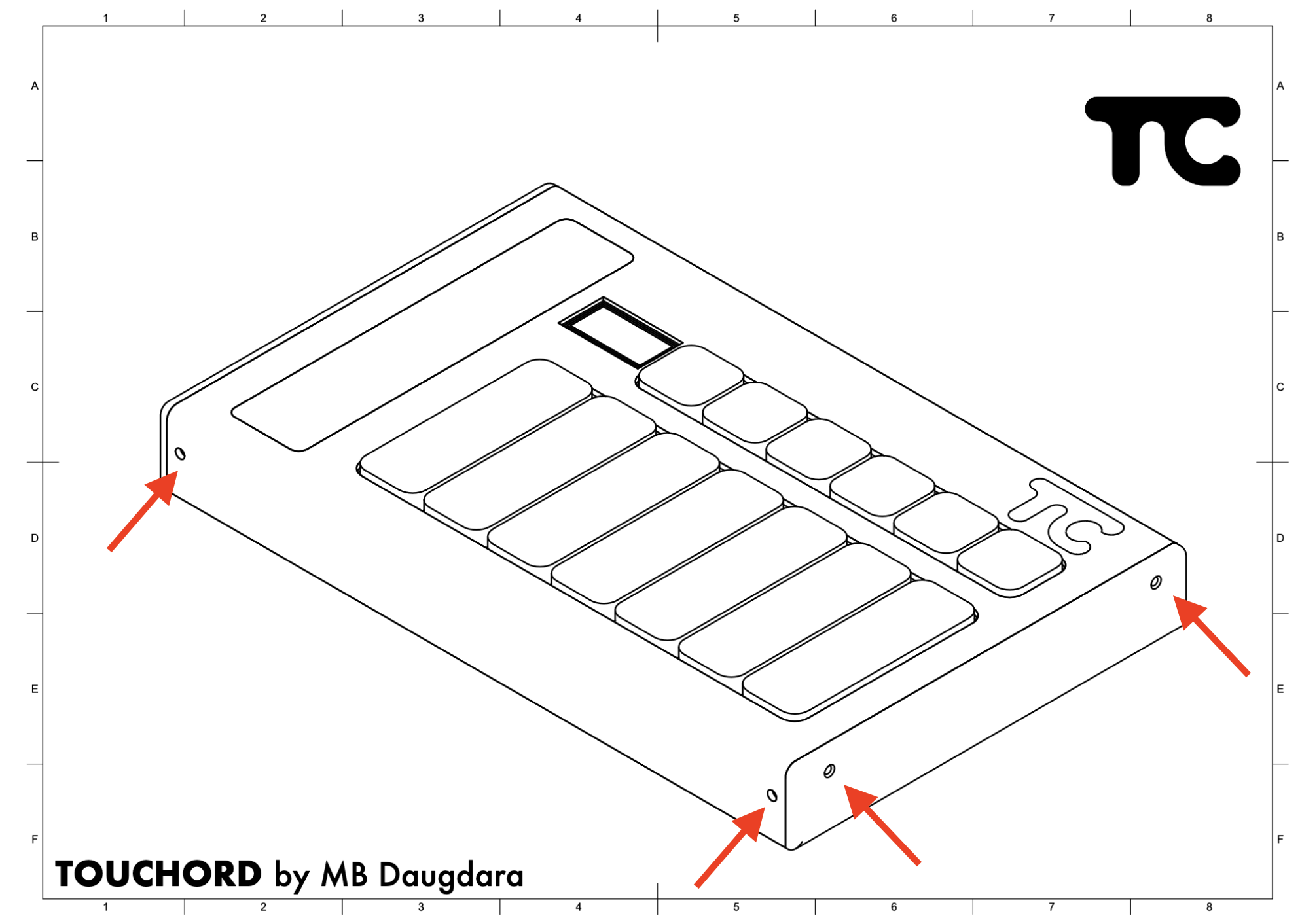
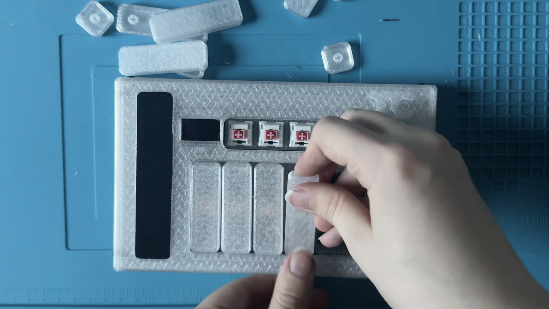
Step 14: Insert the Keys onto Switches
Just place Keys onto the Switches and Stabilizers.
Ending remarks
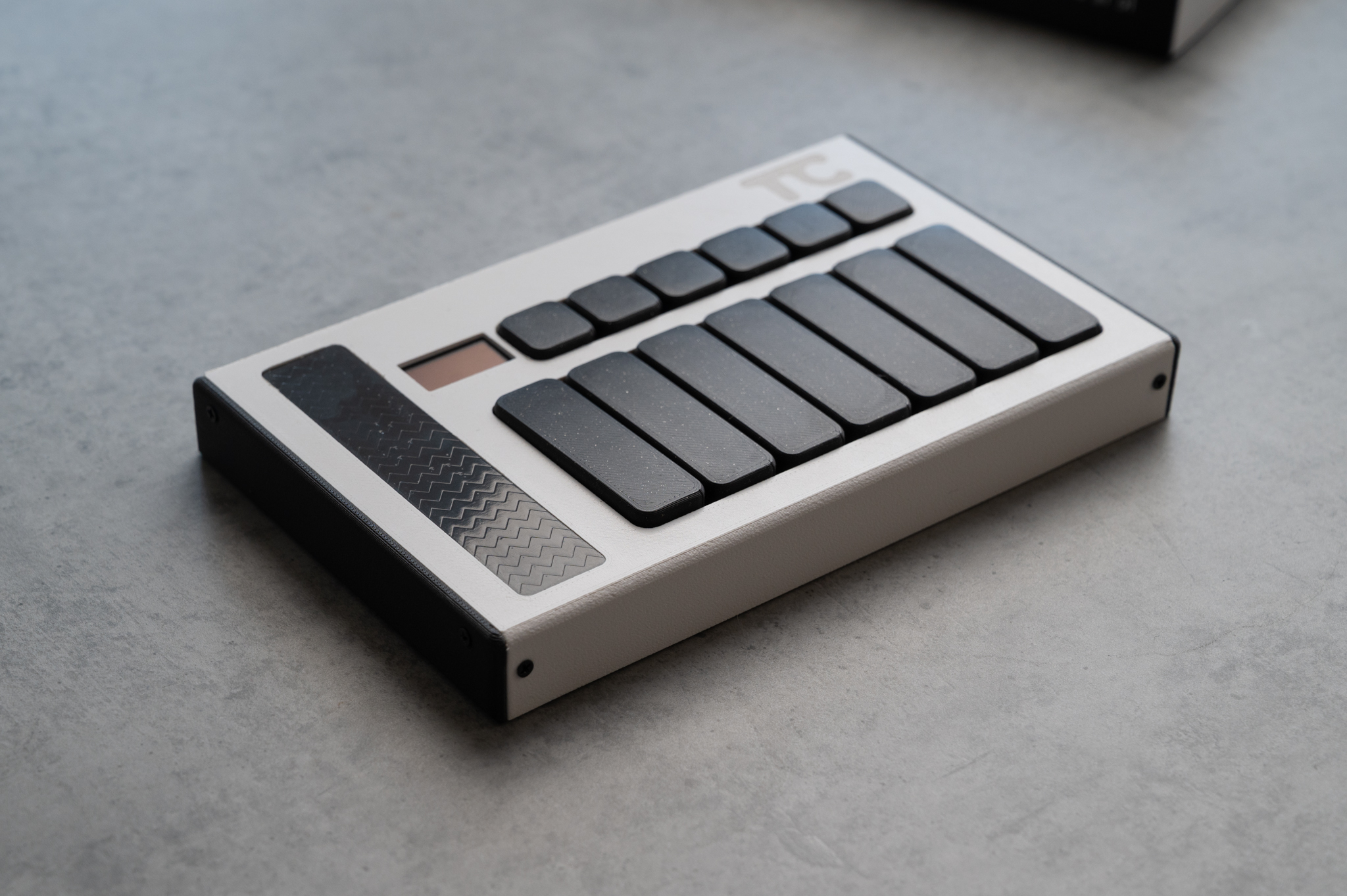
That’s it! now you have a full Touchord unit! Enjoy it, if you notice any issues, want new features, please report them in GitHub.
Updating the firmware
Enter into a BOOTSEL mode
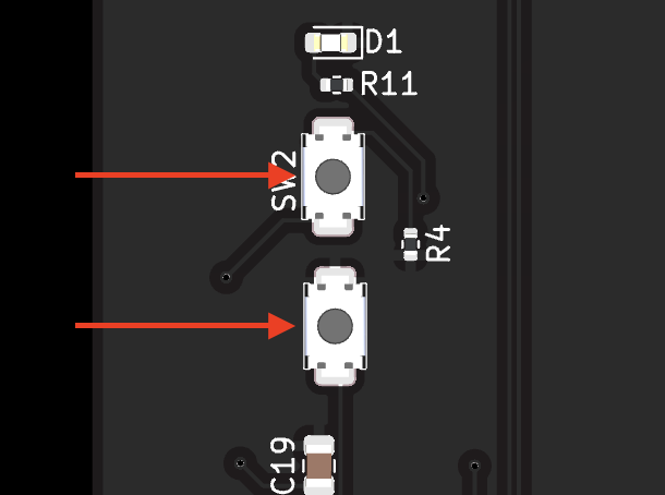
If you have a Bare PCB, something broke or you have a PCB with no Firmware, press these two buttons together, with the Board Plugged into a computer:
If you have a fully assembled PCB, three ways of entering into the bootsel:
- Press B0 + B2 + B4 with Touchord plugged into a Computer;
- Press B0 while plugging Touchord into a Computer;
- Enter Software Update mode in the settings.
Flash the firmware
On your computer a folder/drive called RP2350 should appear. Just drag the firmware file there and Touchord will automatically reboot with flashed firmware. You can Download the latest firmware here. All DIY kits will be “Dual I2C” hardware.